Transair® Aluminum Pipe
Installation Instructions 2"(50mm) – 2-1/2"(63mm)
< Back to Previous Page
Installation Guidelines
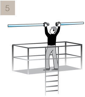
1. Transair pipe and hoses: Transair pipe should be protected from
mechanical impact, particularly if exposed to collision with fork-lift trucks
or when sited in an environment with moving overhead loads. Similarly,
rotation of the pipe and pipe supports should be avoided. Transair pipe
must not be welded.
2. Expansion and contraction: Expansion and contraction of the system
should be calculated prior to installation. The system designer and installer
should calculate the elongation or retraction of each Transair line
according to the recommendations in this installation guide.
3. Situation to avoid: Installation within a solid mass (concrete, foam, etc.),
the hanging of any external equipment to Transair pipe, the use of Transair
for grounding or as a support for electrical equipment, and exposure to
chemicals that are incompatible.
4. When assembling Transair connectors, do not interchange the nuts
with different Transair bodies due to our calibration process.
Tools
Click Here for the Tools Page
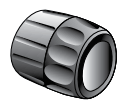
 Pipe cutter for aluminum pipe
ref. 6698 03 01
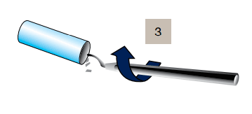
 Chamfer tool for aluminum pipe
ref. 6698 04 01
 Deburring tool for aluminum pipe
ref. 6698 04 02
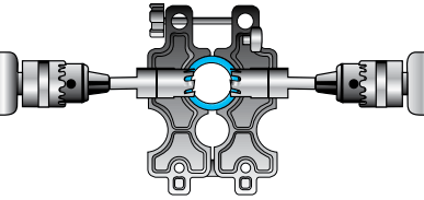
 Drilling jig for aluminum pipe
ref. 6698 01 03
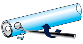
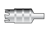 Drilling tool for aluminum pipe
ref. 6698 02 01
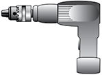 Drill
Drill
Procedure
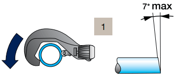
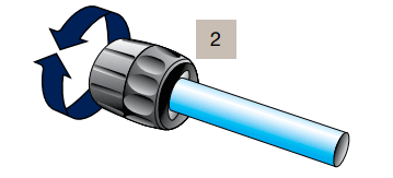
place the pipe in the pipe cutter position the blade onto the pipe rotate the pipe cutter around the pipe while gently tightening the wheel.

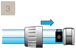
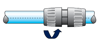
Connection


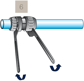
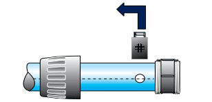
Disconnection
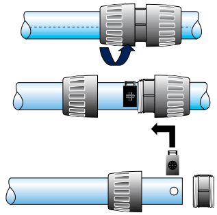
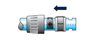
Lateral Dismantling


Back to Main Training Page
Also Available from mdi

 |
TransairPipeSales.com is owned and operated by mdi, Manufacturers Distributor, Inc. mdi is an Authorized Parker Transair Piping System Distributor. Click Here to view the mdi Line Sheet. |